
Definition
A bag filter is a collector or separator of solid particles (dust) within a gaseous stream. The gas is forced through a textile medium, sleeves or bags, which retain the particles. This textile must be periodically cleaned to remove the dust and empty it for later reuse or disposal.
History
Different qualities of filter fabric have been worked with throughout history, as well as numerous cleaning systems, from manual methods to those incorporating advances with mechanical devices, low pressure countercurrent air and different combinations of both.
Industrial applications
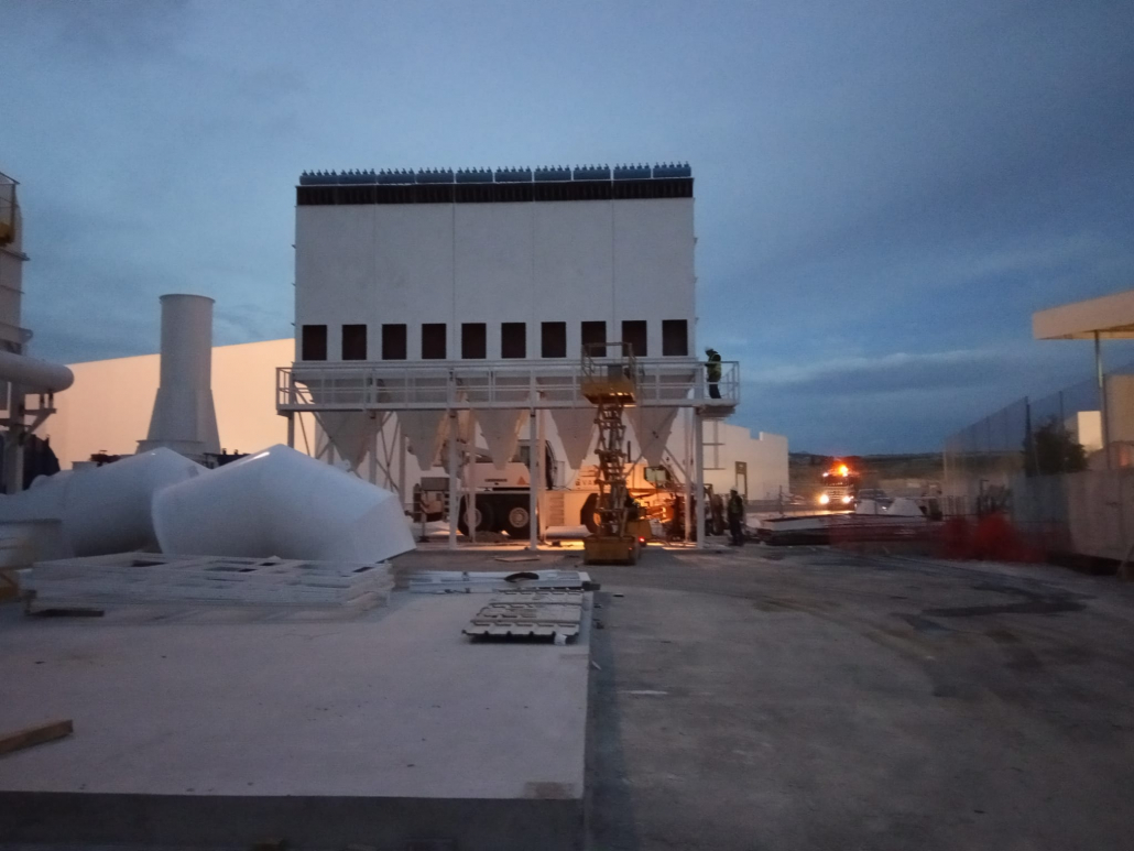
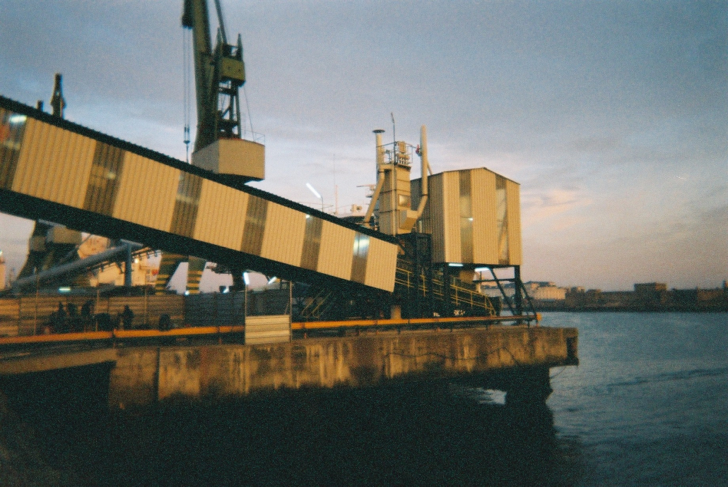
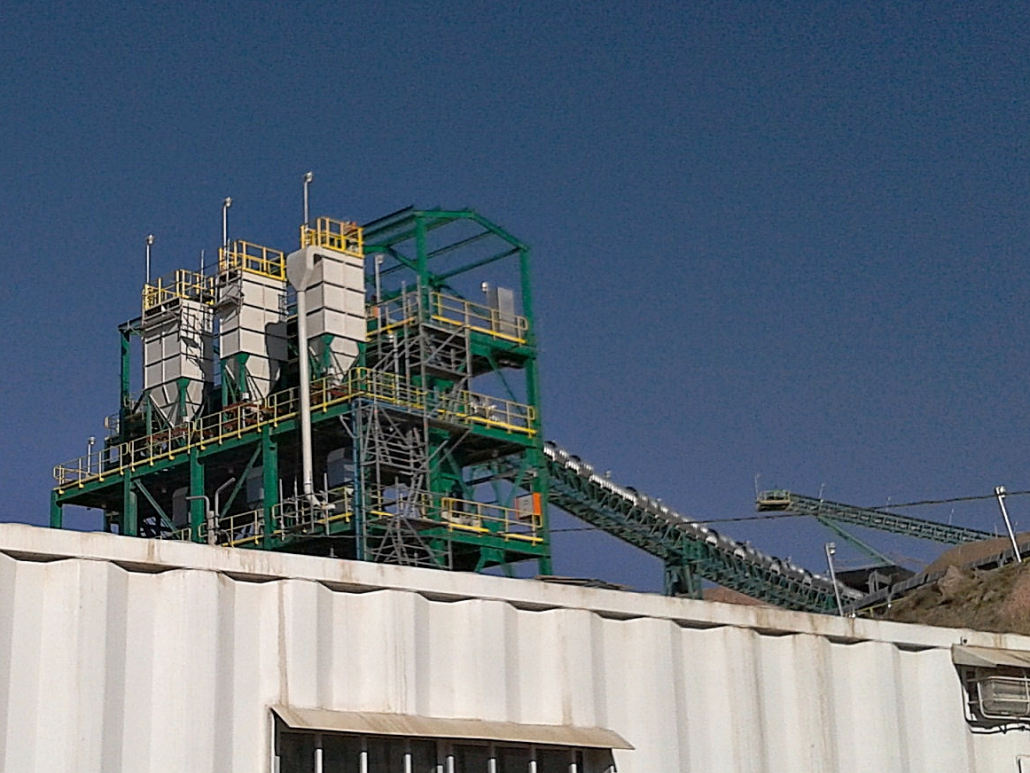
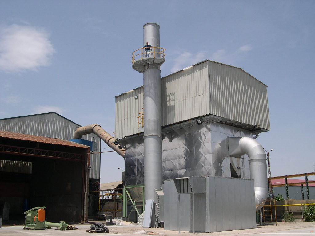
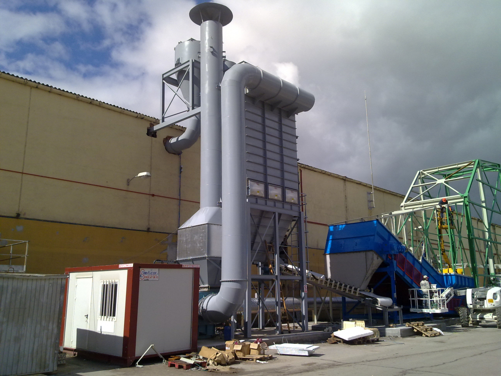
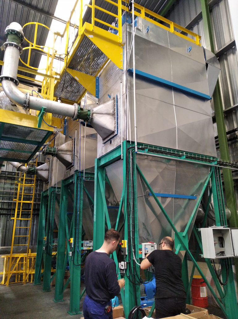
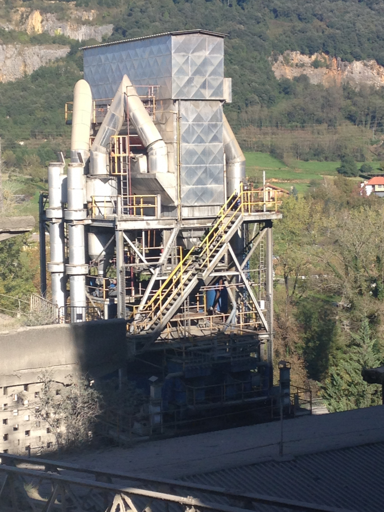
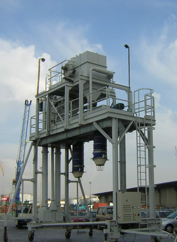
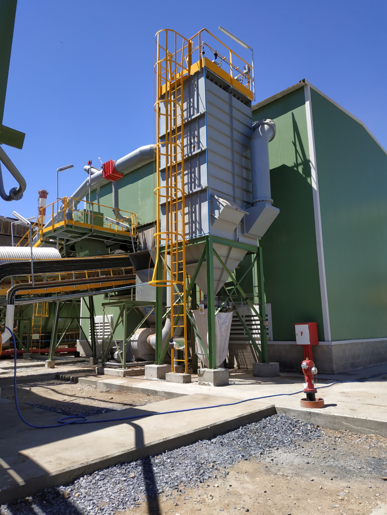
GORCO has provided a vast collection of bag filter types in the last 45 years: in over 3,000 systems of a wide variety of sizes and applications.



Off-line cleaning system
The usual way of cleaning pulse jet filters is by very short (microsecond) impulses of compressed air on a row of bags without stopping the flow of gas through the filter; in a way, the filter “filters” and “cleans” itself simultaneously. This is on-line cleaning, and is usual in a very high percentage of cases; for simplicity, the term on-line is always omitted.
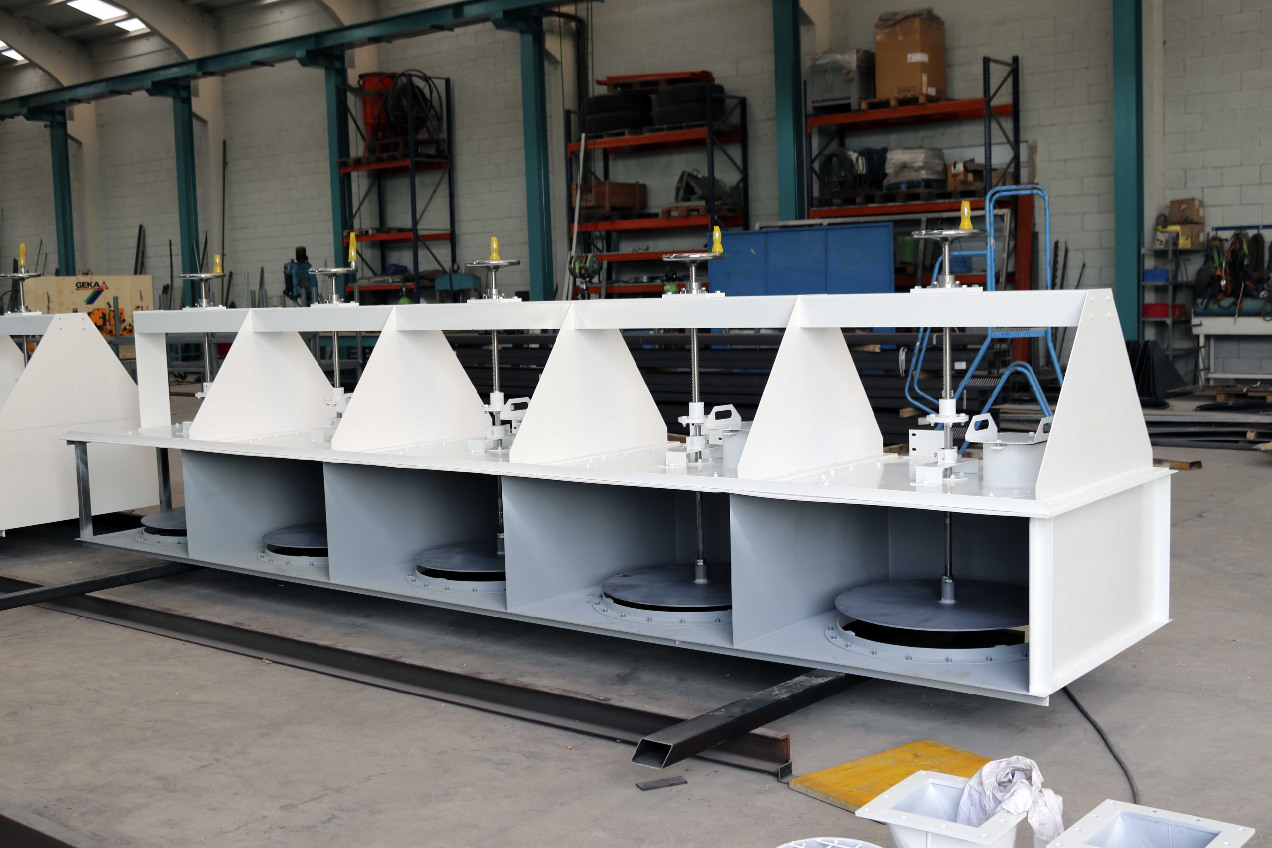
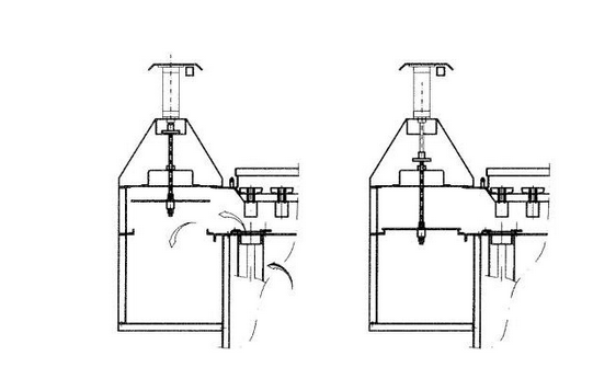
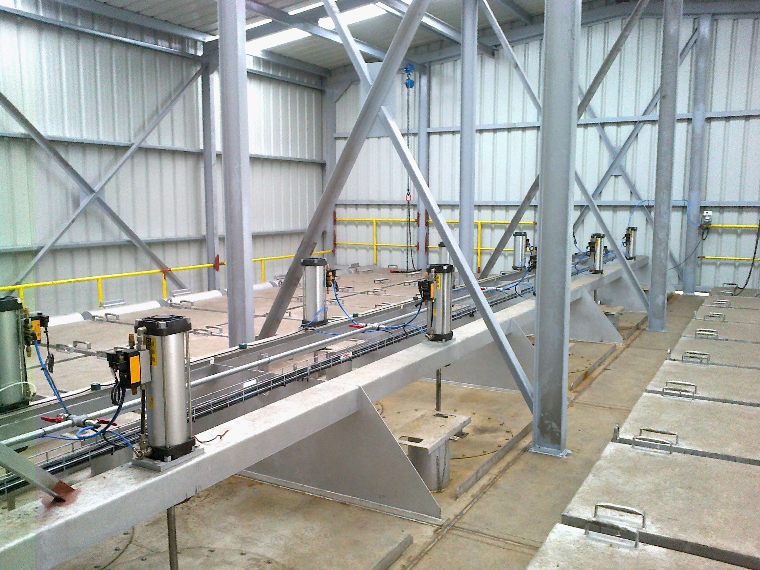
However, in some applications, when it is particularly difficulty to clean the bag, the filter is compartmentalised into separate sections or chambers, with shut-off valves in the clean air zone. In this case, to clean the bags, the fan is switched off, resulting in dust falling from the bag into the dust removal hopper below.
The shut-off valves work automatically from the control PLC, in coordination with the cleaning system.
Filtering and cleaning processes
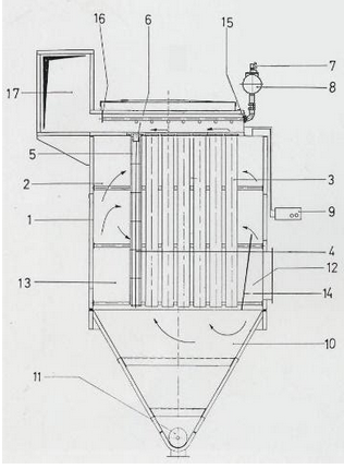
Filtering process
The dust-filled gas enters through the contaminated air inlet (12) and filtration chamber (13). A deflector (14) causes the coarse powder to fall towards the hopper (10), decreasing the filtration system load and preventing the rupture of sleeves by direct abrasion.
The air passes through the sleeves (3) from the outside to the inside and the dust is deposited on the outside of the sleeves.
The sleeves are arranged in rows (4). Each sleeve is mounted on a metal frame or cage (5). The cages are hung from the lower clamping nozzles (6).
Thus, the entire casing (1) constitutes a large contaminated air chamber (2). The dust released according to the cleaning system described below falls into the hopper and the dust extraction bodies (11).
The clean air passes through the sleeves and exits through the clean air channel (17) to the outside, generally sucked in by the draft fan.
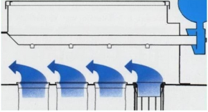
Cleaning process
During the filtration phase, the dust is deposited on the outside of the sleeves, made of high-quality materials.
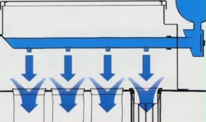
This is achieved by brief injections of compressed air. An electronic control unit (9) actuates the diaphragm valves (7) via solenoid valves so the compressed air goes from the storage tank (8) to the corresponding row of sleeves.
The cleaning cycle ranges from 1 to 10 minutes. The duration of each shot is 0.05 – 0.2 seconds, and the cleaning pressure is 3 to 6 bar (even lower pressure in off-line systems). All these parameters are adjustable.
The compressed air enters the tube on each row of sleeves and exits towards them through the corresponding orifices.
Large amounts of air are effectively drawn into the sleeve by the venturi effect that takes place, producing a maximum amount of cleaning air and optimal unblocking.
The system assembly is extremely simple. Each row is assembled and disassembled in one go by simply loosening the screw (16) and the quick-release fastener in the cable gland (15).
The seal between contaminated air and clean air zones is guaranteed by a lower nozzle clamping system with plate and cap nuts or snap-ring sleeves.
Basic concept “Filtering Ratio”
The filtering ratio (β) is the flow of gas to be filtered (Q) divided by the filter surface area (S).
β = Q/S
Typical Units: m3/h/m2, m3/min/m2, cfm/sq.feet
Theoretically, the smaller the filtering ratio, the harder the filtering problem; while high ratios correspond to simpler problems.
The filter ratio is selected in each case by the filter manufacturer, based on their expertise and experience. GORCO has installed several thousand filtration units in the most diverse applications in its more than 45 years of existence.
Once the filtering ratio to apply has been decided, the filter size is determined directly by the following basic equation:
S (filtering surface area) = Q (gas flow) / β (filtering ratio)
Typical values of β:
| β | easy | intermediate | hard |
| m3/h/m2 | 130 – 200 | 70 – 130 | 40 – 70 |
| m3/min/m2 | 2.2 – 3.3 | 1.2 – 2.2 | 0.7 – 1.2 |
Bag quality
As the textile medium or “bag” is the most important part of the system, it is clear its selection requires the greatest attention.
GORCO works only with first-line national and European fabric suppliers of proven experience and items in responsible applications. Generally, almost all of them are old GORCO suppliers with whom a relationship of trust has been established.
In each case, the most suitable type of needle-punched felt is established according to criteria of efficiency, durability, operating temperature and the specific gas and dust conditions experienced.
GORCO SA is, therefore, able to guarantee chimney emission values below those required by the corresponding regulations at all times, and according to customer specifications.
The highest quality bags are made of:
POLYESTER – ACRYLIC – POLYPROPYLENE – ARAMIDS (NOMEX) – PPS (RYTON, PROCON)
– PI, POLYIMIDE (P 84) – GLASS FIBRE – PTFE (TEFLON) – Various combinations of these
